CNC Milling vs. Turning: Which Process Fits Your Part's Geometry and Tolerances
Stress Relief and Finishing Decide the Long Game
Material Selection Sets the Ceiling for Strength
Strength starts long before the first cut, with picking the right metal for the job. The wrong grade underperforms no matter how skilled the welding is. Mild steel handles general framing well. Where loads run higher or fatigue is a concern, a higher strength low alloy steel earns its place. For wet or corrosive settings, 304 or 316 stainless changes the entire lifespan picture.
Thickness matters as much as grade. A frame built from material even a sixteenth of an inch too thin can flex under repeated load, and that flex works the welds loose over time. We match grade and thickness to the real conditions a part will see, not the average case, and everything after that decides how close to the ceiling the finished part gets.
How Local Humidity and Sandy Soil Change the Approach
Quick Answer: CNC milling and CNC turning remove material in opposite ways, and that difference decides which one belongs on your drawing. Turning spins the workpiece against a fixed cutting tool, which is why it produces round, concentric features — shafts, bushings, threaded fittings — and can hold diametral tolerances down to a few ten-thousandths of an inch. Milling holds the workpiece still and spins the tool instead, which is what lets it cut pockets, bolt patterns, and flat mounting faces that a lathe can't reach. Few real parts are purely one or the other — a shaft with a keyway, a housing with a bored bearing seat — so the decision usually comes down to which process carries the part's tightest, most functionally critical features, with the second process picking up whatever the first one can't.
A print crosses your desk with a bored bearing seat on one end and a six-hole bolt pattern on a flange at the other. Both features carry tight tolerances, but they don't belong to the same process family, and specifying the wrong one first is how a part ends up needing a second setup, a second fixture, and a second trip through inspection that nobody budgeted for. Milling and turning aren't interchangeable options for the same job — they're two different ways of removing metal, and each one is naturally good at features the other one struggles with. Knowing which is which before the drawing gets released is what keeps a design engineer's part off the rework pile.
Two Ways of Cutting Metal, Two Different Results
Turning holds the workpiece in a rotating chuck or collet and feeds a stationary, single-point tool into it as it spins. Because the cut happens continuously around a rotating axis, the process naturally produces cylinders, cones, and other round profiles — shafts, sleeves, threaded studs, valve bodies. The workpiece does the moving; the tool mostly just travels along it.
Milling reverses that relationship. The workpiece is clamped to a table and stays put while a rotating, multi-point cutter — an end mill, face mill, or ball-nose tool — moves across it on multiple axes. That's what allows milling to cut features that don't have rotational symmetry at all: pockets, slots, stepped faces, bolt-hole patterns, and free-form 3D contours.
The practical rule of thumb.
If a part's defining features are round — an outside diameter, a bore, a thread — start with turning. If the defining features are flat, angular, or patterned — a mounting face, a series of drilled and tapped holes, a machined slot — start with milling. Most parts that look "simple" from across the shop floor actually need a combination of both, just in different proportions.
Match the Process to the Part's Geometry First
Before tolerances or finish enter the conversation, geometry alone eliminates one process or the other for most features.
Turning's natural territory
Anything with a length-to-diameter relationship along a single axis — shafts, spindles, bushings, collars, threaded fasteners, and nozzles — falls squarely into turning's strength. Grooves, tapers, undercuts, and both internal and external threads are all routine turning operations. And because the cut runs continuously around a rotating part, turning tends to move faster than milling on parts that start out round.
Milling's natural territory
Prismatic parts — housings, brackets, plates, gear blanks, and enclosures — need milling because their critical features can't come from spinning the part. A flat mating face, a bolt circle, a keyway, a pocket cut for a bearing or a cable channel: none of that is reachable on a lathe. Complex 3D surfaces, like mold cavities or contoured impellers, are milling work almost by definition.
Where the two overlap
A part with a turned outside diameter that also needs a hex flat, a cross-drilled hole, or a keyway needs both processes in sequence — turning for the round features, milling for everything that breaks rotational symmetry. This is common enough in production parts that it's worth flagging on the drawing early, since it affects fixturing and the number of setups a shop has to plan for.
Tolerances, Concentricity, and Positional Accuracy Aren't the Same Problem
This is where a lot of process-selection mistakes happen. Engineers sometimes treat "tight tolerance" as a single spec that either process can hit, when in practice turning and milling are good at different *kinds* of tightness.
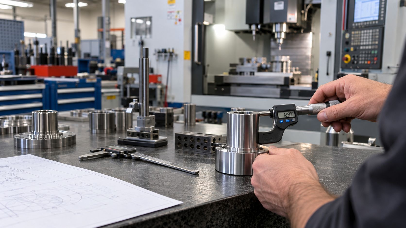
Turning excels at diametral tolerances and concentricity — how close a rotating feature's actual center sits to its intended axis. Because the part rotates against a fixed tool through the entire cut, roundness and concentricity come almost for free with the process. On a bearing journal or a sealing diameter, that matters more than almost any other spec on the print.
Milling excels at positional accuracy and flatness — how precisely a hole, pocket, or face sits relative to other features on the part. A bolt-hole pattern that has to line up with a mating housing, or a mounting face that has to sit flat against another surface, is a milling problem, not a turning one, because milling's multi-axis table control is what locates features relative to each other.
Under ASME Y14.5 geometric dimensioning and tolerancing conventions, concentricity and true position are called out as distinct tolerance types for exactly this reason — they control different things about a feature's location, and they're achieved by different processes. Standard machining tolerances on most industrial shop floors run around ±0.005 inch, with high-precision features tightened to as close as ±0.0001 inch depending on equipment rigidity, tooling condition, and the inspection method a job calls for. Which features get which tolerance, and which process delivers it, is a decision that should happen at the design stage — not after the drawing is released.
Tip: If your part has both a critical round feature and a critical positional feature — say, a turned bore that has to align with a milled bolt pattern — call out which one is the primary datum on the drawing. That single decision tells the shop which process to machine first and keeps the second operation referencing the feature that actually matters most to your assembly.
Surface Finish Follows the Process, Not Just the Tolerance
Surface finish and dimensional tolerance are related but not the same thing, and it's easy to over-spec one while under-thinking the other. Turning, because the cut is continuous and the tool path is simple, tends to produce smoother finishes on round surfaces with less programming effort — sealing diameters and bearing seats often reach a fine finish as a natural byproduct of a well-tuned turning operation. Milling finishes depend more heavily on stepover, tool selection, and cutting parameters, and interrupted cuts across pockets or contoured surfaces generally take more passes to reach the same smoothness a lathe delivers on a round part in a single pass.
None of that means milling can't produce a fine finish — ball-nose finishing passes and secondary operations like surface grinding routinely bring milled features to tight flatness and low roughness when a design calls for it. It means the two processes get there differently, and specifying a finish requirement without knowing which process is producing that surface can add unnecessary cycle time chasing a finish the geometry doesn't naturally support.
Material Behavior Shifts the Calculus Too
Process selection doesn't happen in a vacuum from material choice. Free-machining materials like brass and certain aluminum alloys cut fast and clean under either process, but harder or gummier materials change the math. Stainless steel work-hardens under interrupted cuts, which can make certain milling operations more demanding than the equivalent turning pass on the same alloy. Titanium's low thermal conductivity concentrates heat at the cutting edge regardless of process, but the continuous engagement of a turning operation manages that heat differently than the repeated tool entries of a milling pass. None of this changes which process a given geometry needs — a round feature is still a turning feature no matter the material — but it does affect cycle time, tool wear, and how aggressively a shop can run the job once the process is chosen.
When One Process Alone Isn't Enough
Most parts that look purely "turned" or purely "milled" from a drawing actually need a secondary operation once you look closely. A shaft with a keyway needs turning for the diameter and a milling pass for the flat. A valve body with a threaded boss and cross-drilled ports needs both operations sequenced carefully so the round features and the positional features reference the same datum. Some shops handle this with mill-turn centers that combine a turning spindle with live milling tools in a single setup, cutting down on the re-fixturing that would otherwise introduce stack-up error between operations; others sequence the part through separate turning and milling operations with a documented fixturing plan. Either approach can hold tight tolerances across both feature types — the difference is in setup count, handling, and how the shop manages datum continuity between operations.
Where a feature needs something neither process delivers well — a hardened part with a fine internal keyway, or a detailed cavity cut into tool steel — wire or sinker EDM and surface grinding often step in as secondary operations. That's better than forcing milling or turning to do something neither one is built for.
Warning: Don't assume a shop can simply "mill it instead" to skip a second setup on a part with round, concentric features that actually matter to the assembly. Trying to hold a tight diametral tolerance and concentricity spec with a milling operation instead of turning usually costs more time than the sequencing it was meant to avoid. The roundness rarely matches what a lathe produces as a matter of course, either.
Industries Where Getting This Right Actually Matters
In food-processing equipment, mixing shafts and bearing housings both show up on the same assembly — the shaft needs turning to hold concentricity against a rotating seal, while the housing needs milling to align mounting bolts and o-ring grooves correctly. Get the process wrong on either one and the seal leaks or the housing doesn't seat.
Aerospace-grade components frequently demand both operations on a single part, with documented traceability at each step — a landing gear pin or actuator shaft machined on a lathe, paired with a milled bracket or housing that has to locate against dozens of fastener positions. Medical-device parts push the same logic further: implant-grade turned components need concentricity that holds up under repeated inspection, while milled surgical instrument bodies need positional accuracy across small, closely spaced features. In all three industries, the process decision isn't a shop-floor detail — it's a design decision that determines whether the part functions as intended the first time it's built.
Frequently Asked Questions
Can a single part need both CNC milling and turning?
Yes. Many parts combine round and non-round features, making both processes necessary. Turning handles bores, shafts, and threads, while milling creates slots, flats, pockets, and bolt patterns. They can be sequenced separately.
Which process holds a tighter tolerance, milling or turning?
Neither process is universally more precise. Turning typically excels at diameters, roundness, and concentricity, while milling performs well for positional accuracy, flatness, and feature relationships. The required tolerance determines the better process.
Does turning always produce a better surface finish than milling?
Turning often produces excellent finishes on round surfaces because cutting is continuous. However, milling can achieve comparable or superior finishes on flat and contoured surfaces through appropriate tooling, cutting parameters, finishing passes, and secondary grinding.
How do I know which process my part needs before I finalize the drawing?
Identify the part's critical functional features and determine whether they are round or non-round. Then establish the primary datum and required tolerances. This helps determine process order, fixturing requirements, and appropriate machining methods.
Is mill-turn machining always better than sequencing separate operations?
Not necessarily. Mill-turn machining can reduce setups and improve alignment between turned and milled features. However, separate operations may be equally effective when features have less demanding relationships, making traditional sequencing practical, reliable, and economical.
What materials are hardest to machine with either process?
Titanium and hardened stainless steels can challenge both milling and turning because they generate heat, resist cutting, or work-harden. Proper tooling, cutting speeds, feeds, coolant, and machining strategies help control tool wear and maintain accuracy.
Precision Machining Guided By Geometry And Tolerance
In Seven Lakes, NC, Savant Industrial Products & Services brings 13 years of precision machining experience to parts that require both dimensional control and practical process planning. Understanding how geometry, material, surface finish, and tolerance requirements interact makes it easier to select an efficient machining strategy without adding unnecessary operations.
Whether a component is primarily turned, milled, or requires both, the machining process should support the features that are most critical to how the part functions. When process selection is considered early, manufacturers can achieve consistent results while reducing setup complexity and avoiding avoidable tolerance problems.