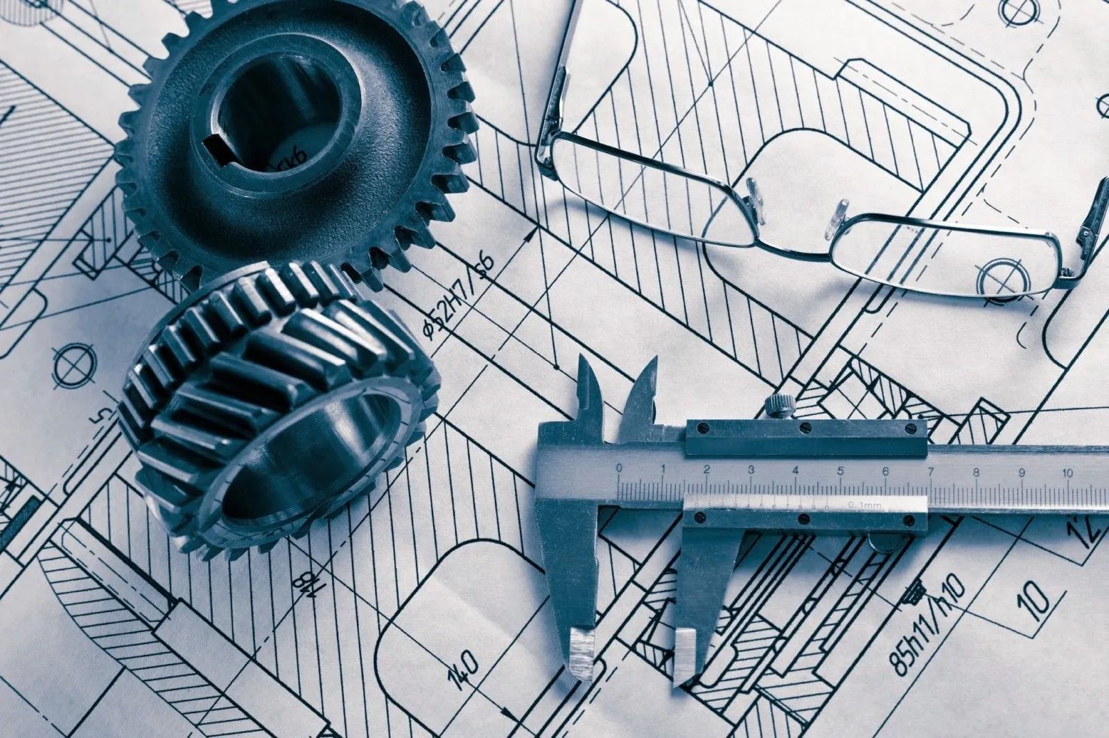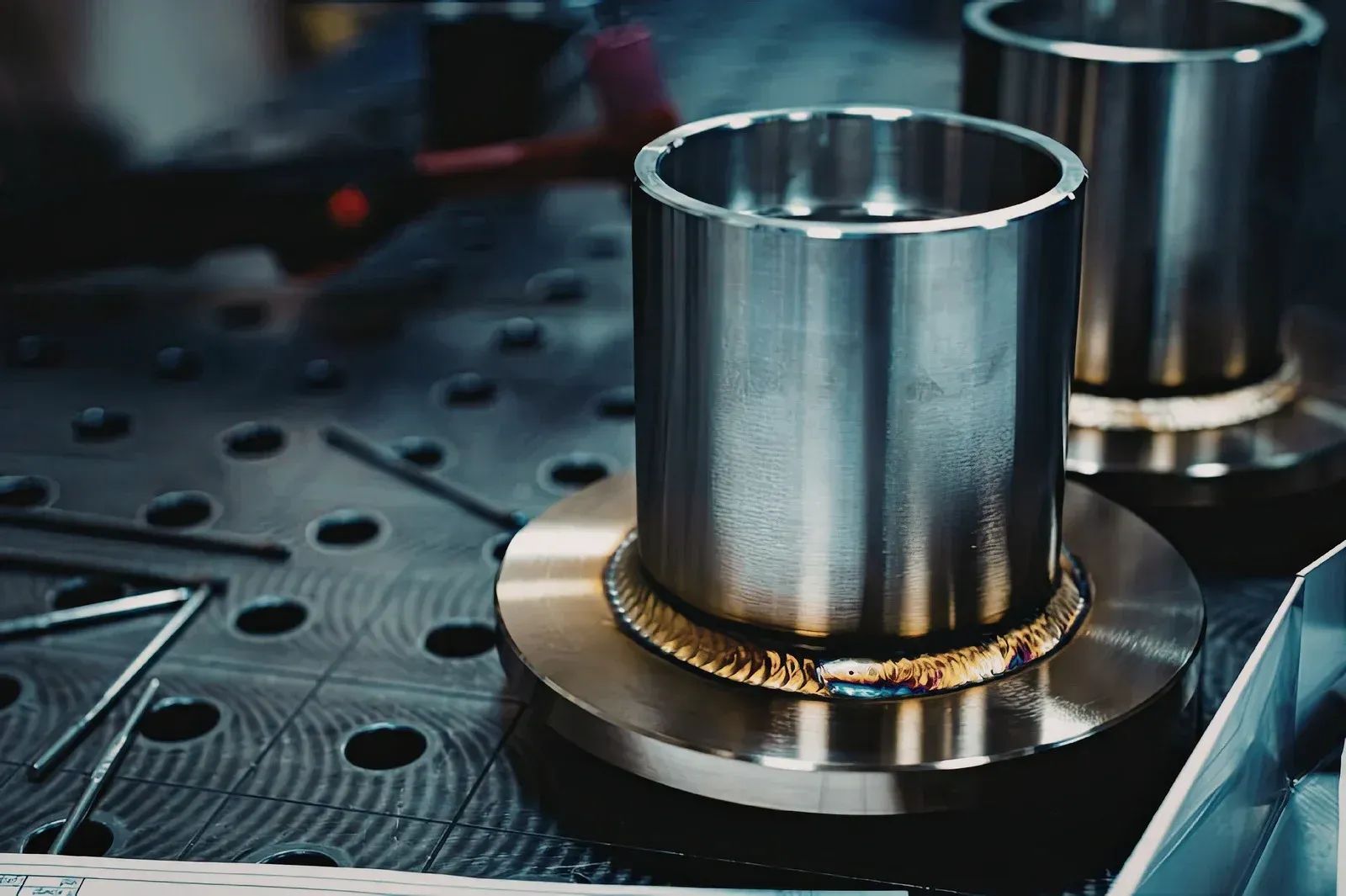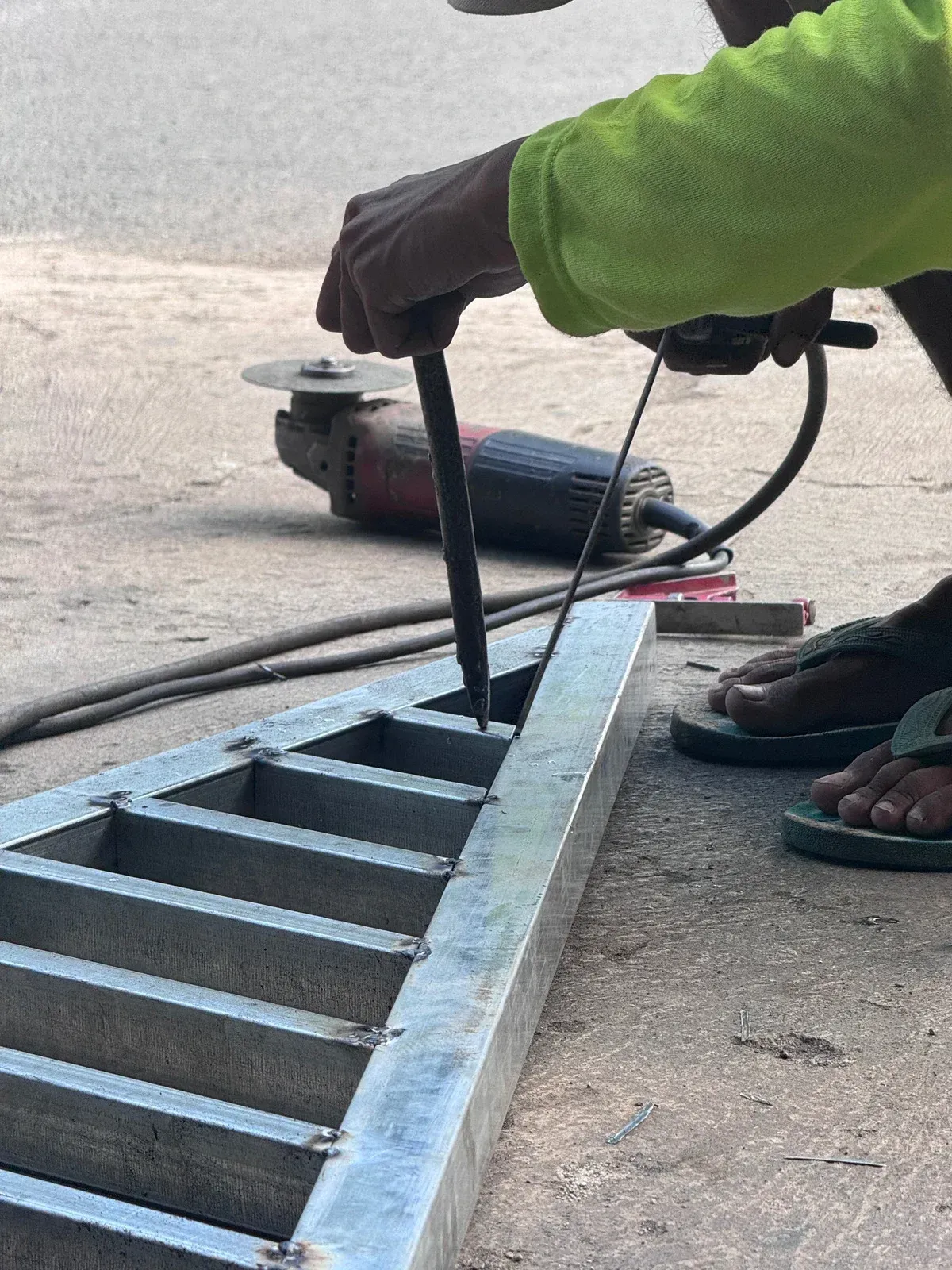
Tight Tolerances Explained: What "Plus or Minus a Thousandth" Really Means
Stress Relief and Finishing Decide the Long Game
Material Selection Sets the Ceiling for Strength
Strength starts long before the first cut, with picking the right metal for the job. The wrong grade underperforms no matter how skilled the welding is. Mild steel handles general framing well. Where loads run higher or fatigue is a concern, a higher strength low alloy steel earns its place. For wet or corrosive settings, 304 or 316 stainless changes the entire lifespan picture.
Thickness matters as much as grade. A frame built from material even a sixteenth of an inch too thin can flex under repeated load, and that flex works the welds loose over time. We match grade and thickness to the real conditions a part will see, not the average case, and everything after that decides how close to the ceiling the finished part gets.
How Local Humidity and Sandy Soil Change the Approach
Quick Answer: A "thousandth" in machining is 0.001 inch — about a quarter the width of a sheet of paper — and a callout like ±0.001" means the finished dimension can land anywhere in that 0.002" window and still pass inspection. Standard shop-floor tolerances on most industrial parts run around ±0.005", while tight-tolerance work tightens that to ±0.001" or less, and high-precision features can hold as close as ±0.0001" with the right equipment and process controls. ASME Y14.5 is the governing standard behind how these tolerances get written and read on a drawing in the US, and it works alongside plain plus/minus dimensioning for features that don't need full geometric dimensioning and tolerancing. The tighter the number, the more it costs in cycle time, tooling, and inspection — so the goal on any print is the loosest tolerance that still makes the part work, not the tightest one a shop can technically hit.
A supplier drawing lands on your desk with a bore callout of Ø0.7500" +0.0005/-0.0000, and the quote that comes back is noticeably higher than the last batch you ordered. Nobody explains why in the email. And you know the part needs to fit, but you're not sure whether that half-thousandth is doing real work in the assembly or whether someone copied a tolerance block from an old drawing and never revisited it. That gap — between a number on a print and what it actually costs to produce and prove — is where a lot of quotes go sideways, and it's worth closing before the drawing gets released.
This isn't really about decimal points. It's about understanding what a shop has to do differently to hit a given number, and matching that number to what the part actually needs to function. Get that right and the tolerance becomes a design tool instead of a mystery line item.
What a Thousandth Actually Is
An inch splits into a thousand equal parts, and each of those parts is a thousandth — written as 0.001". For scale, a standard sheet of printer paper runs about 0.004" thick, so a single thousandth is roughly a quarter of that. Ten thousandths, sometimes just called "ten tenths" on the shop floor, equal 0.010" — about the diameter of a strand of hair on the coarser end.
When a print calls out a dimension as ±0.001", it's telling the machinist and the inspector that the finished feature can fall anywhere inside a 0.002" band centered on the target number and still be an acceptable part. A 1.000" shaft diameter toleranced at ±0.001" is good anywhere from 0.999" to 1.001". That's the whole window — not a suggestion, not a target to split exactly down the middle, just a range the part has to land inside.
Tolerances can also be asymmetric, like the +0.0005/-0.0000 example above. That kind of one-sided callout usually means the feature has to be at or above nominal but never below it — common on a bore that has to clear a mating shaft, where oversize is safe and undersize is a scrap part.
The Tolerance Ladder, From General Purpose to Ultra-Precision
Not every feature on a part needs the same level of control, and shops generally think in tiers rather than treating every dimension as equally demanding.
General Purpose
Roughly ±0.005" to ±0.020", covering most structural features, housings, and non-mating surfaces. This is what most CNC shops, including Savant, treat as their everyday baseline — accurate enough for the bulk of industrial parts without requiring special process controls.
Precision
Around ±0.002" to ±0.005". This band shows up on mechanical assemblies, gear-mounting features, and bearing bores where parts have to seat correctly but don't need extreme repeatability.
High Precision
Roughly ±0.0005" to ±0.002". Here, tolerances start affecting equipment selection, workholding, and cycle time in a real way. Optical mounts, gauge bodies, and critical sealing diameters often live in this range.
Ultra Precision
Tighter than ±0.0005", sometimes down to ±0.0001". This is the territory of semiconductor tooling, research instruments, and the most demanding aerospace and medical features — and it requires equipment, environmental control, and inspection gear built specifically for that level of repeatability.
Where the line between "standard" and "tight tolerance" actually falls depends on who you ask and what industry the part serves. Aerospace engineers sometimes treat anything past ±0.001" as tight; a shop running general fabrication work might not blink until a print asks for ±0.0005" or tighter. What matters isn't the label — it's whether your specific feature falls into a band that changes how the shop has to run the job.
Where ASME Y14.5 Fits Into a Tolerance Callout
Most US drawings that call out tolerances, whether through simple plus/minus dimensioning or full geometric dimensioning and tolerancing (GD&T), are built on ASME Y14.5. The standard originated from military drawing requirements in the 1940s and has been revised several times since, with the 2018 edition (reaffirmed in 2024) as the current version most shops and design teams reference today.
Y14.5 does two things a design engineer actually relies on. First, it standardizes plus/minus tolerancing itself — the rules for how a dimension's tolerance is interpreted, including default tolerances implied by the number of decimal places in a title block when no explicit tolerance is called out. A dimension written as 2.50 typically defaults to a looser tolerance than one written as 2.500, purely because of how many decimal places appear — which is exactly the kind of detail that trips up a print reviewed too quickly.
Second, Y14.5 defines the symbols and rules behind full GD&T: position, flatness, concentricity, runout, and the datum structure that ties a feature's location back to a reference surface. GD&T controls things plus/minus tolerancing alone can't — how round a bore actually is, not just its diameter, or how precisely a bolt pattern sits relative to a mounting face. Outside North America, ISO 2768 plays a similar role for general tolerances on drawings that don't call out GD&T explicitly, and it's worth flagging on a print if a part will be manufactured or inspected against a global supply chain that defaults to metric conventions.
None of this means every print needs full GD&T. Plenty of parts function fine with straightforward plus/minus dimensioning on the features that matter. But knowing which system a drawing is using, and why, keeps a tolerance callout from becoming a guessing game between the design team and the shop floor.
Why Tighter Isn't Automatically Better
A tolerance that's tighter than the part needs doesn't make the part better. It just makes it more expensive, and the relationship between tolerance and cost isn't a straight line — it curves upward fast.
Cutting a feature to ±0.005" and cutting the same feature to ±0.0005" aren't the same job scaled down. The tighter callout usually means slower feeds and speeds to control heat and deflection, more rigid workholding to eliminate part movement mid-cut, sharper or higher-grade tooling that wears predictably, and a measurement step that can actually confirm the part hit spec. Each of those adds time, and time is the biggest lever on a machined part's price.
Rejection rates climb too. A process that comfortably holds ±0.005" all day might see its scrap rate jump once the same feature gets toleranced to ±0.0005", simply because there's less room for normal process variation — tool wear over a run, small temperature shifts in the shop, material variation batch to batch — to land inside the window.
None of that is an argument against tight tolerances where they're actually needed. It's an argument for calling them out only where the part's function genuinely depends on that level of control, and leaving everything else at a tolerance the process can hold comfortably and repeatably.
Tip: Before a drawing goes out for quote, walk through each toleranced dimension and ask what actually breaks if that feature came in at the loose end of a general-purpose tolerance instead. If nothing in the assembly changes, the tolerance is probably tighter than it needs to be, and loosening it can shave real cost off the quote without touching how the part performs.
How a Shop Actually Hits a Thousandth
Holding a tight tolerance consistently, not just on one lucky part but across a whole run, comes down to a handful of things working together.
Equipment Rigidity And Calibration
A machine with excess spindle runout or a worn ballscrew can produce a part that's in spec today and out tomorrow. Shops running tight-tolerance work maintain a calibration schedule and match the machine to the job rather than assuming any CNC center can hold any number.
Workholding
A part that shifts even a few tenths of a thousandth during a cut ruins the tolerance no matter how good the machine is. Precision fixtures, properly torqued clamping, and repeatable locating features matter more as the tolerance tightens.
Tooling And Cutting Parameters
Sharper, more consistent tooling — sometimes ground carbide or coated inserts rather than standard stock tooling — combined with reduced speeds and feeds, keeps cutting forces and heat from pushing a feature out of window.
Thermal Control
Metal expands and contracts with temperature, and a part measured warm off the machine can read differently once it cools to room temperature. Shops chasing tight tolerances typically let parts stabilize before final inspection, and some control shop temperature itself for the most demanding work.
Measurement Capability
This is the part engineers sometimes overlook. A common rule of thumb in quality control calls for measurement equipment accurate to at least ten times finer than the tolerance being checked — so verifying a ±0.001" feature calls for a gauge or CMM that resolves well past that number, not a dial caliper eyeballed to the nearest thousandth. Without that measurement margin, a shop can't actually prove the part is in spec, tight tolerance or not.
Material matters here too. Aluminum generally machines predictably to tight tolerances because it cuts cool and holds its shape well under the tool. Stainless steel work-hardens under repeated or interrupted cuts, which can push a dimension out of window if cutting parameters aren't adjusted for it. Titanium's low thermal conductivity concentrates heat right at the cutting edge, which affects both tool life and dimensional stability on tight-tolerance features. None of that rules a material out of tight-tolerance work — it just changes what the process has to account for.
Reading a Tolerance Callout Without Guessing
A few habits make tolerance callouts easier to interpret correctly, on a drawing someone else made or one you're writing yourself.
Check whether the tolerance is symmetric or one-sided. ±0.002" is centered on nominal either direction; +0.004/-0.000 only allows growth in one direction. Mixing those up when reading a print is an easy way to end up with a part that's technically out of spec even though it "looks close."
Look at what the tolerance is actually controlling. A diameter tolerance controls size. A position or concentricity callout under full GD&T controls location or roundness relative to a datum — a tighter size tolerance doesn't automatically buy tighter location, and the two get specified separately for a reason.
Warning: Don't assume a tighter tolerance on one feature automatically improves how that feature relates to the rest of the part. A bore machined to a razor-thin diameter tolerance can still sit off-center relative to a mounting face if nothing on the print calls out its position or concentricity. Size and location are controlled independently, and a print that only tightens size while leaving location loose can still produce a part that doesn't assemble correctly.
Finally, note which features actually need the tight number and which are riding along on a blanket tolerance block. A print with a single general tolerance note applied to every dimension often ends up tighter than necessary on features that don't need it, simply because nobody broke the tolerance out feature by feature.
When a Tight Tolerance Is Actually Worth Calling Out
Certain functional situations genuinely need the tighter end of the tolerance ladder, and it pays to recognize them rather than defaulting every print to the same number out of habit.
Rotating assemblies with press fits or bearing seats depend on precise diametral control — too loose and the fit spins or leaks; too tight and the parts won't assemble without damage. Sealing surfaces, whether an O-ring groove or a mating flange, need tight enough control that the seal actually compresses evenly across its full circumference. Mating parts machined by different processes or in different batches — a shaft from one run meeting a housing from another — rely on tight tolerances to guarantee interchangeability without hand-fitting each pair.
Regulated or safety-critical industries push this further. Aerospace fittings and structural components carry tight tolerances because the consequences of an out-of-spec dimension scale up fast. Medical device components need tight, repeatable tolerances because inconsistency between units isn't an acceptable outcome when the part interacts with a patient. Food-processing equipment often combines tight dimensional control with a specific surface finish, since both affect how cleanable and hygienic a component stays in service.
Outside those cases, a tolerance that's merely tight because it's always been written that way on the drawing template is worth a second look before the print goes out for quote.
Frequently Asked Questions
What's the difference between a "standard" tolerance and a "tight" tolerance?
There's no single line, since it depends on industry and application. Most shops treat anything looser than ±0.005 inch as standard, and ±0.001 inch down to ±0.0001 inch as tighter work needing careful process control.
How much does tightening a tolerance actually add to the cost of a part?
The relationship isn't linear, since tightening a tolerance by one order of magnitude can add meaningfully more cost, because it usually triggers slower cutting speeds, tighter workholding, extra inspection steps, and a higher scrap rate.
Can a machine shop hold ±0.0001" on any material?
Not equally well. Aluminum and other free-machining materials hold tight tolerances more predictably than stainless steel or titanium, which work-harden or concentrate heat differently under the tool, needing slower speeds and specialized tooling to compensate.
Do I need full GD&T, or is a plus/minus tolerance enough?
It depends on what the feature controls. Plus/minus dimensioning suits size features with no tie to another surface. Full GD&T matters when a feature's location or orientation to a datum carries equal weight to size.
Why did my quote go up when I only tightened one dimension?
A single tightened dimension can change the whole process plan, not just that feature. It might require a different fixture, a slower cutting pass, a dedicated inspection step, or equipment the shop wouldn't otherwise need.
How is a tolerance verified once the part is machined?
Verification depends on the tolerance. Simple size tolerances are checked with calipers, micrometers, or pin gauges for looser callouts, and a CMM or optical comparator for tighter ones. GD&T features need a CMM or gauge.
Matching Tolerance to What the Part Actually Needs
A tolerance callout is only useful when it reflects what the part has to do once it leaves the shop, not how impressive the number looks on a drawing. Reading a ±0.001 inch callout correctly, knowing where ASME Y14.5 applies, and identifying which features carry functional weight turns a print review into a conversation between design and the shop floor. That conversation, held early, keeps cost proportional to performance instead of letting an old template decide the number nobody revisited.
Savant Industrial Products & Services
has built 13
years of precision
machining and fabrication work
out of Seven Lakes, North Carolina, running ISO-based quality controls across every job that crosses the shop floor. That process discipline is what makes a tight tolerance achievable in the first place, not just written on paper. A print that pairs the right number with the right process becomes a part that fits, functions, and holds up as intended, without surprises once it reaches assembly.